Why PCB controls 50 ohm impedance
single-ended network in the design is generally controlled by 50 ohms, so many people will ask, why is it required to be controlled by 50 ohms instead of 25 ohms or 80 ohms? First of all, 50 ohms is selected by default, and everyone in the industry accepts this value. Generally speaking, it must be a standard set by a recognized organization, and everyone designs according to the standard.
Using the reference clock to realize serial communication data recovery of Cyclone10LP devices
In the non-source synchronous low-speed serial data communication scenario, the clock frequency of the communication counterpart may be biased, which may cause the data receiving end to be unable to accurately sample. In this case, the SOFT-CDR and DPA functions in the high-speed transceiver or LVDS serdes of high-end Altera devices can effectively solve this problem.
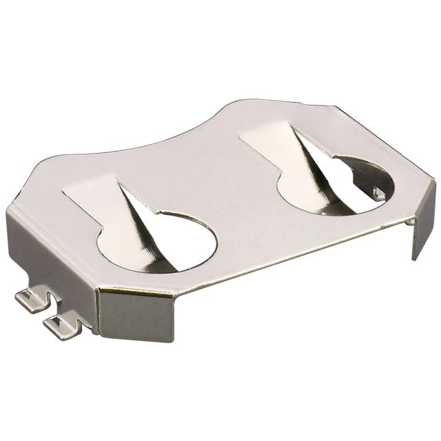
CR2032 vs CR2450 batteries: Which one is better for your device?
Many daily devices use CR2032 and CR2450 batteries because of their small size and reliable performance.
7408 Integrated Circuit: A Classic TTL (transistor-transistor logic) Type IC
The 7408 integrated circuit is a classic TTL (transistor-transistor logic) type IC, which is widely used in various digital circuits. It contains four 2-input AND gates, each with two inputs and one output, for performing logical AND operations.
What is Transistor hFE
hFE, also known as current gain or β (Beta), is an important parameter of the transistor, which represents the ratio between the base current and the collector current. It describes the gain capability of a transistor when amplifying current.
IGBT vs. MOSFET: A Comprehensive Comparison of Features
Both IGBTs and MOSFETs are important semiconductor devices that are widely used in power electronics, switching power supplies, and other high-power control systems. They can both be used to control the flow of current, but their operating principles, characteristics, and application scenarios differ.
WiFi 7 vs WiFi 6: Wireless Network Routing Comparison
WiFi 7 (802.11be) and WiFi 6 (802.11ax) are both wireless network communications standards, but they have significant differences in performance, spectral efficiency, latency, and the number of devices they support.
ENIG vs ENEPIG PCB: Explore the Difference
The choice of PCB surface finish is more than just a detail; it determines the performance and lifespan of the PCB. The versatile and robust Electroless Nickel Electroless Palladium Immersion Gold (ENEPIG) and the reliable and classic Electroless Nickel Immersion Gold (ENIG).
The automotive crystal oscillator FA-238A is the preferred choice for car Bluetooth
Epson FA-238A is a high-performance quartz crystal oscillator widely used in automotive, industrial and consumer electronics fields. It is particularly suitable for automotive-grade and high-reliability applications, with excellent temperature stability, low power consumption and high precision.
What are the differences between tantalum capacitors and ordinary capacitors
Tantalum capacitors are often used in high-precision circuits due to their high reliability, stability and small size, but due to their high price and polarity requirements, special attention should be paid to the connection polarity during design.
What is a clamping diode? Principle, function and application analysis
Clamping diodes are a common electronic component, also known as protection diodes or baropendulum diodes.
Four Common Topological Approaches to Powering LEDs
There are many topologies that can be used to power LEDs. As you probably already know, you need to first identify your design requirements before you start selecting, or you may end up with a design that is less than ideal or, worse, not guaranteed to work properly over the long term.
Regionalization Trend of Global Electronic Component Manufacturing: The Impact of Multinational Joint Ventures and Supply Chain Diversification
As global supply chain pressure increases, more and more electronic component companies are establishing production bases in places such as India and Southeast Asia, promoting the regionalization of supply chains.
US CHIPS Act 2024 in-depth implementation: How to reshape the global semiconductor supply chain and the future of technology
In August 2024, as the CHIPS Act is further promoted, the United States strives to localize the semiconductor industry and reduce external dependence. This strategic transformation is reshaping the global chip supply chain and is crucial to the future development of emerging technology fields such as AI and big data. This article deeply analyzes how the CHIPS Act reshapes the global supply chain and brings key industry impacts.
Hisense TVs sold out in Walmart on Black Friday
During this year's Black Friday promotion, Hisense TVs once again became a hot-selling product in the United States. Recently, a large number of videos of Americans rushing to buy Hisense TVs appeared on social media.
What is a clamping diode? Principle, function and application analysis

Understanding Clamping Diodes
Clamping diodes, also known as protection diodes, are crucial components in electronics, offering protection and voltage control in circuits. They possess unique voltage response characteristics, which make them essential for limiting voltage levels and safeguarding circuit components. Typically made from materials like silicon, germanium, or silicon carbide, clamping diodes provide high-speed response and minimal leakage current.
Working Principle of Clamping Diodes
Clamping diodes operate by conducting current when a specific voltage threshold is exceeded.
- Negative Terminal Grounded:If the positive terminal's voltage rises above ground, the diode conducts, clamping the voltage to nearly zero or slightly below (disregarding the diode's forward voltage drop).
- Positive Terminal Grounded:When the voltage at the negative terminal rises above ground, the diode remains off, leaving the circuit unaffected by the diode's operation.
The critical voltage level at which the diode begins conducting is known as the clamp voltage, serving as the control point for voltage limitation.
Functions of Clamping Diodes
- Voltage Limiting:Clamping diodes restrict the voltage within a circuit to a predefined range, protecting components from excessive voltage levels.
- Circuit Protection:When voltages exceed safe operating levels, the diode conducts, redirecting excess voltage to ground or a safe pathway, thereby safeguarding sensitive components.
- Waveform Shaping:In signal processing, clamping diodes help maintain a desired waveform by eliminating voltage spikes or distortions.
- Voltage Stabilization:These diodes can assist in voltage regulation, ensuring consistent operation of the circuit by maintaining stable voltage levels.
Types of Clamping Diode Circuits
According to the circuit structure, the clamp diode has two circuit modes, one is a simple type and one is a bias type.
Simple positive clamp circuit
Circuit principle: When the input Vin is negative half a week (Vin is negative and positive), the diode is switched on, the current is shown as the red arrow, the capacitor is charged to V (left negative and right positive), Vout=0V; When the input Vin is in positive half cycle (Vin is positive and negative on the bottom), the diode is cut off, the current is shown as the blue arrow, Vout voltage is equal to the capacitor voltage plus positive half cycle voltage, so Vout=2V;

Simple positive clamp circuit
Simple negative clamp circuit
Circuit principle: Input Vin in positive half week (Vin is positive and negative), diode conduction, current as shown by the red arrow, capacitor at both ends of the differential pressure charge to V (left positive and right negative), Vout=0V;
When the input Vin is negative half cycle (Vin is negative and positive on the bottom), the diode is cut off, the current is shown as the blue arrow, and the Vout voltage is equal to negative (capacitor voltage negative half cycle voltage), that is, Vout=-2V;

Simple negative clamp circuit
Bias type positive clamp circuit
A bias clamp circuit is similar to a limiter circuit in that a bias voltage is added to the circuit to raise or lower the clamp value.
Figure a shows the forward bias type. When the bias applied is consistent with the diode conduction direction, the waveform is upward, that is, the clamp value will increase V1.
Figure b shows the reverse bias type. When the bias applied is opposite to the diode conduction direction, the waveform is downward, that is, the clamp value will decrease V1.
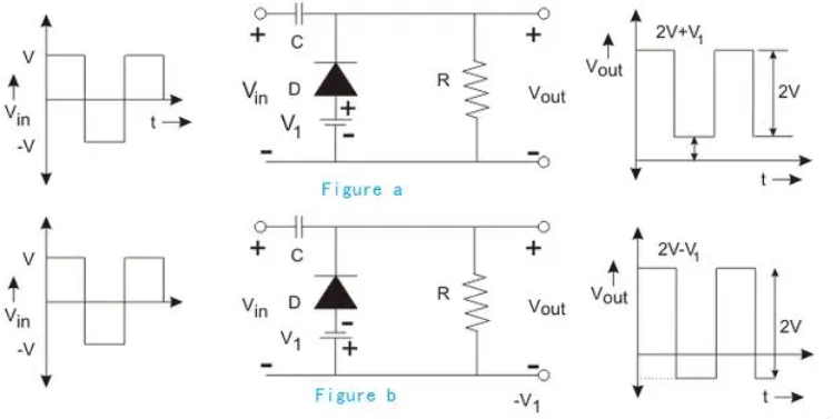
Bias type positive clamp circuit
Bias type negative clamp circuit
A biased negative clamp is similar to a biased positive clamp in that a bias voltage is added to the circuit to raise or lower the clamp value.
Figure C shows the reverse bias type. When the bias applied is opposite to the diode conduction direction, the waveform is upward, that is, the clamp value will increase V1.
Figure D shows the forward bias type. When the bias applied is the same as the diode conduction direction, the waveform is downward, that is, the clamp value will decrease V1.
ALSO READ: Exploring the Zener Diode| Definition, Uses & Fuctions
Applications of Clamping Diodes
- Signal Limiting:Clamping diodes act as signal limiters in communication systems, ensuring signal amplitudes remain within a safe range to protect receivers.
- Voltage Regulation:Used in power supplies, clamping diodes stabilize input voltage fluctuations, providing steady voltage for sensitive devices like computers and measuring instruments.
- Temperature Compensation:Due to their temperature-dependent forward voltage drop, clamping diodes can be paired with thermistors for temperature stabilization.
- Waveform Correction:In analog circuits, these diodes can eliminate noise and distortions from input signals, improving waveform stability.
- Voltage Detection:Clamping diodes are used in voltage detectors to monitor and respond to specific voltage thresholds, triggering alerts or circuit actions.
Clamping Diodes vs. Zener Diodes
- Clamping Diodes: Limit voltage to protect circuits by conducting during overvoltage events.
- Zener Diodes: Primarily used for voltage regulation, maintaining a steady reverse breakdown voltage.
In comparator designs, clamping diodes limit the output voltage range, ensuring it stays within safe boundaries and protClamping Diodes in Comparator Circuitsecting subsequent components.
FAQs About Clamping Diodes
1.Q:What is the primary role of a clamping diode?
A:Clamping diodes limit voltage to safeguard circuits from spikes, transient surges, and other overvoltage events.
2.Q:How do clamping diodes differ from Zener diodes?
A:Zener diodes regulate voltage in reverse bias, while clamping diodes prevent overvoltage in either direction.
3.Q:Why are clamping diodes used in signal circuits?
A:Clamping diodes stabilize signal amplitudes and prevent voltage spikes, ensuring reliable circuit performance.
