Using the reference clock to realize serial communication data recovery of Cyclone10LP devices
In the non-source synchronous low-speed serial data communication scenario, the clock frequency of the communication counterpart may be biased, which may cause the data receiving end to be unable to accurately sample. In this case, the SOFT-CDR and DPA functions in the high-speed transceiver or LVDS serdes of high-end Altera devices can effectively solve this problem. However, for mid-to-low-end devices such as Cyclone IV or Cyclone 10LP, they have neither high-speed transceivers nor LVDS serdes that support SOFT-CDR and DPA functions, so we need to design logic to realize serial data recovery.
The trick of this design is to use the reference clock of the receiving end, and oversample the received data by 8 times by the rising and falling edges of the two clocks with a phase shift of 0° and 90°, and then use logic to determine how to select a stable clock domain, and use the data sampled in this clock domain as reliable data.

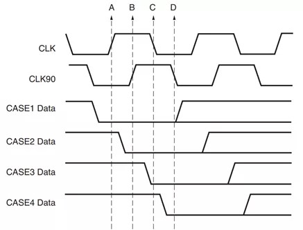
Figure 1
As shown in Figure 1, the first trigger is sampled by the rising edge of CLK described as time domain A, the second trigger is sampled by the rising edge of time domain B, i.e. CLK90, the third trigger is sampled by time domain C, i.e. CLK falling edge, and the fourth trigger is sampled by time domain D, i.e. CLK90 falling edge.
Of course, in order to eliminate metastability, it is definitely not enough to use only one level of sampling. It is necessary to perform four levels of sampling on these four triggers to eliminate metastability, as shown in Figure 2:

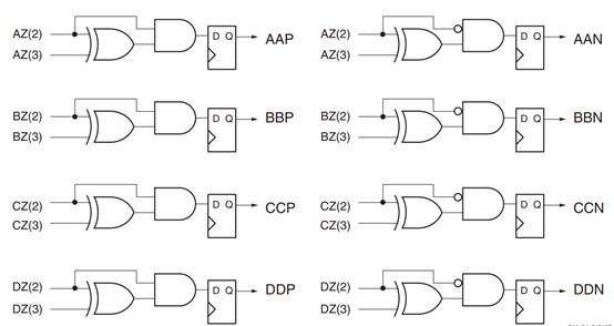
Figure 2
After we perform trigger sampling step by step according to Figure 2, we name the third level triggers AZ(2), BZ(2), CZ(2), and DZ(2); and the fourth level triggers AZ(3), BZ(3), CZ(3), and DZ(3).
After the data is sampled at four levels in four clock domains, a combinational logic is performed, as shown in Figure 3:

Figure 3
According to Figure 3, after performing XOR, AND/NAND logic in turn, the data AAP, AAN, BBP, BBN, CCP, CCN, DDP, and DDN are obtained in turn through the trigger;
After that, a reliable clock domain judgment is required, that is, the clock domain with the most stable sampling data is selected:

In actual situations, we may encounter: for example, the clock frequency of the data transmitter is 401MHz, while the local sampling clock frequency is 400MHz, or vice versa, the transmitter is 400MHz, while the local is 401MHz; through simulation, it is found that in this case, the judgment result will change periodically, that is, the clock domain judged to be stable may change from D to A after a period of time, but this does not matter. According to the clock domain judged to be the most reliable, the actual data obtained in the end must be correct.
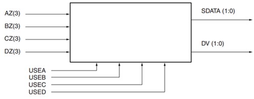
Since the judgment result of the reliable clock domain will change, we need to design a small piece of logic to filter the data, as shown in Figure 4:

Figure 4
The main purpose of this design is to find the most reliable clock domain that can stably sample data, even if this clock domain may change dynamically due to the clock frequency deviation of the communication peer, the sampling data based on this clock domain is stable and reliable. At present, based on the hardware of an industrial customer, I have verified the serial communication of data based on 10CL010YU256C8G and 10CL016YU256C8G, and tested the pseudo-random code communication for a long time, and the bit error rate is 0; the relevant products of this customer have been mass-produced. Of course, for more reliable communication quality, we will also add 8B10B codec modules to actual products.


