STM32F103C8T6 Microcontroller: A High-Performance, Low-Power Solution for Embedded Systems

Hedy · Dasenic Jun 28,2024 216

The STM32F103C8T6 is a high-performance, low-power 32-bit microcontroller designed by STMicroelectronics based on the ARM Cortex-M3 core. As part of the STM32 family, this microcontroller belongs to the F1 series and is a popular mid-range model widely used in various embedded systems and industrial control projects.

Core Features:

  • Processor Core: The STM32F103C8T6 utilizes the ARM Cortex-M3 architecture, operating at a maximum frequency of 72MHz. It supports the Thumb-2 instruction set, providing efficient code execution for a wide range of applications.
  • Memory Capacity:Flash Memory: 64KB for storing firmware and constant data, ensuring stable system operation.SRAM: 20KB used as runtime workspace for storing variables and intermediate results, enhancing system responsiveness.

Package and Pins:

  • Package Type: The STM32F103C8T6 comes in an LQFP48 package with 48 pins, making it suitable for integration in compact spaces.

Peripheral Resources:

  • Communication Interfaces: Includes multiple USART (Universal Synchronous/Asynchronous Receiver/Transmitter), SPI (Serial Peripheral Interface), and I2C (Inter-Integrated Circuit) interfaces, supporting various serial communication protocols for device interconnectivity.
  • Timers: Features multiple general-purpose and advanced timers for pulse-width modulation (PWM), input capture, output compare, and quadrature encoder interface, providing precise control and timing capabilities.
  • ADC (Analog-to-Digital Converter): Equipped with up to 12-bit resolution ADC modules for sampling and converting multiple analog signals, enabling high-precision data acquisition.
  • GPIO (General-Purpose Input/Output): Multiple GPIO ports supporting various configuration modes such as push-pull output, open-drain output, and analog input, adaptable to diverse application needs.
  • Additional Peripherals: Includes watchdog timers, CRC calculation units, RTC (Real-Time Clock), SysTick timer, and several interrupt sources, ensuring system stability and functional expansion.

Power and Operating Conditions:

  • Operating Voltage Range: 2.0V to 3.6V, accommodating different power environments.
  • Operating Temperature Range: Commercial grade ranges from -40°C to +85°C, while the extended industrial grade ranges from -40°C to +105°C, meeting various environmental requirements.

Boot Configuration and Programming:

  • Boot Configuration: Configured via BOOT0 and BOOT1 pins. Typically, for system memory boot mode, set BOOT0 to 1 and BOOT1 to 0 to boot from internal flash memory.
  • Programming and Debugging: Supports SWD (Serial Wire Debug) and JTAG debugging interfaces, allowing program download and online debugging through tools like ST-Link or Keil MDK, greatly facilitating development and maintenance.

Application Fields:

The STM32F103C8T6 is widely used in smart hardware, IoT devices, industrial automation control, motor drives, consumer electronics, smart home systems, and wireless communication due to its high cost-effectiveness and comprehensive features.

Summary:

The STM32F103C8T6 microcontroller is an ideal choice for embedded systems and industrial control fields due to its high performance, low power consumption, and diverse peripheral resources. Whether in smart hardware or IoT devices, the STM32F103C8T6 offers reliable solutions, helping developers achieve more efficient and stable application designs.

For more information about the STM32F103C8T6, please visit STMicroelectronics Official Website


STM32F103C8T6 programming
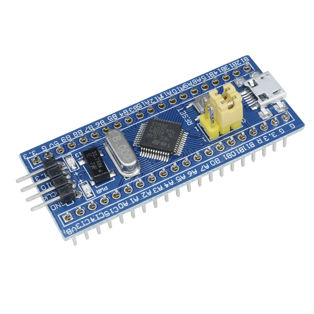
How to program stm32f103c8t6, you need to follow these steps:


1. Preparation

Hardware

STM32F103C8T6 development board: You can use a development board (such as STM32 Blue Pill) or a bare chip.

Programmer/debugger: Such as ST-Link V2, J-Link, etc. ST-Link V2 is the officially recommended tool.

Connection cable: Used to connect the programmer to the development board.

Software

Integrated development environment (IDE): It is recommended to use STM32CubeIDE, which is the official free integrated development environment of ST. You can also use Keil MDK, IAR Embedded Workbench, etc.

STM32CubeMX: A graphical configuration tool that helps you configure the peripherals of the microcontroller and generate initialization code.

ST-Link driver: Make sure the ST-Link driver is installed on your computer so that you can program and debug through ST-Link.


2. Install and set up the development environment

Download STM32CubeIDE:

Download and install STM32CubeIDE from the STMicroelectronics website. This IDE integrates a compiler, debugger, code editor, and other tools.

Install STM32CubeMX:

If you use STM32CubeIDE, it has already integrated STM32CubeMX; otherwise, you can download STM32CubeMX separately.

Install ST-Link driver:

Make sure you install the ST-Link driver so that the IDE can recognize the ST-Link programmer.


3. Configure the microcontroller using STM32CubeMX

Launch STM32CubeMX:

Open STM32CubeMX and create a new project. Select STM32F103C8T6 as the target microcontroller.

Configure peripherals:

In STM32CubeMX, configure the required peripherals (such as GPIO, USART, TIM, etc.). You can do this by clicking on each peripheral and selecting the configuration option.

Generate code:

After configuration, click the "Project" tab to set the project name, location, and IDE (select STM32CubeIDE or other). Then click "Generate Code" to generate the initialization code.


4. Develop code in STM32CubeIDE

Open the project:

Open STM32CubeIDE, select "File" > "Import" > "Existing Projects into Workspace", and then select the project you generated in STM32CubeMX.

Write application code:

In STM32CubeIDE, find the main.c and stm32f1xx_it.c files in the Src and Inc folders, and write the application code.

Compile the project:

Click "Project" > "Build All" to compile and ensure there are no errors.


5. Programming and debugging

Connect the programmer:

Use ST-Link to connect the SWD interface (SWDIO, SWCLK, GND and VCC) of the development board.

Download the program:

In STM32CubeIDE, select "Run" > "Debug" to download the program and start the debugging session. The IDE will automatically program and start debugging.

Debug and test:

Using the debugging function of STM32CubeIDE, you can debug your code by setting breakpoints, viewing variables, stepping execution, etc.


With the above steps, you can successfully program and debug the STM32F103C8T6.

  • RFQ